A ferrule drawing typically carries four tolerances and no note about how they interact. Bore diameter, outer diameter, the concentricity between the two, and the end-face geometry are not independent numbers: tighten one and the others move, because every step between the mold and the final lap spends part of the same budget. Understanding that budget is what separates a drawing that can be molded from one that gets quoted three times and built by nobody.
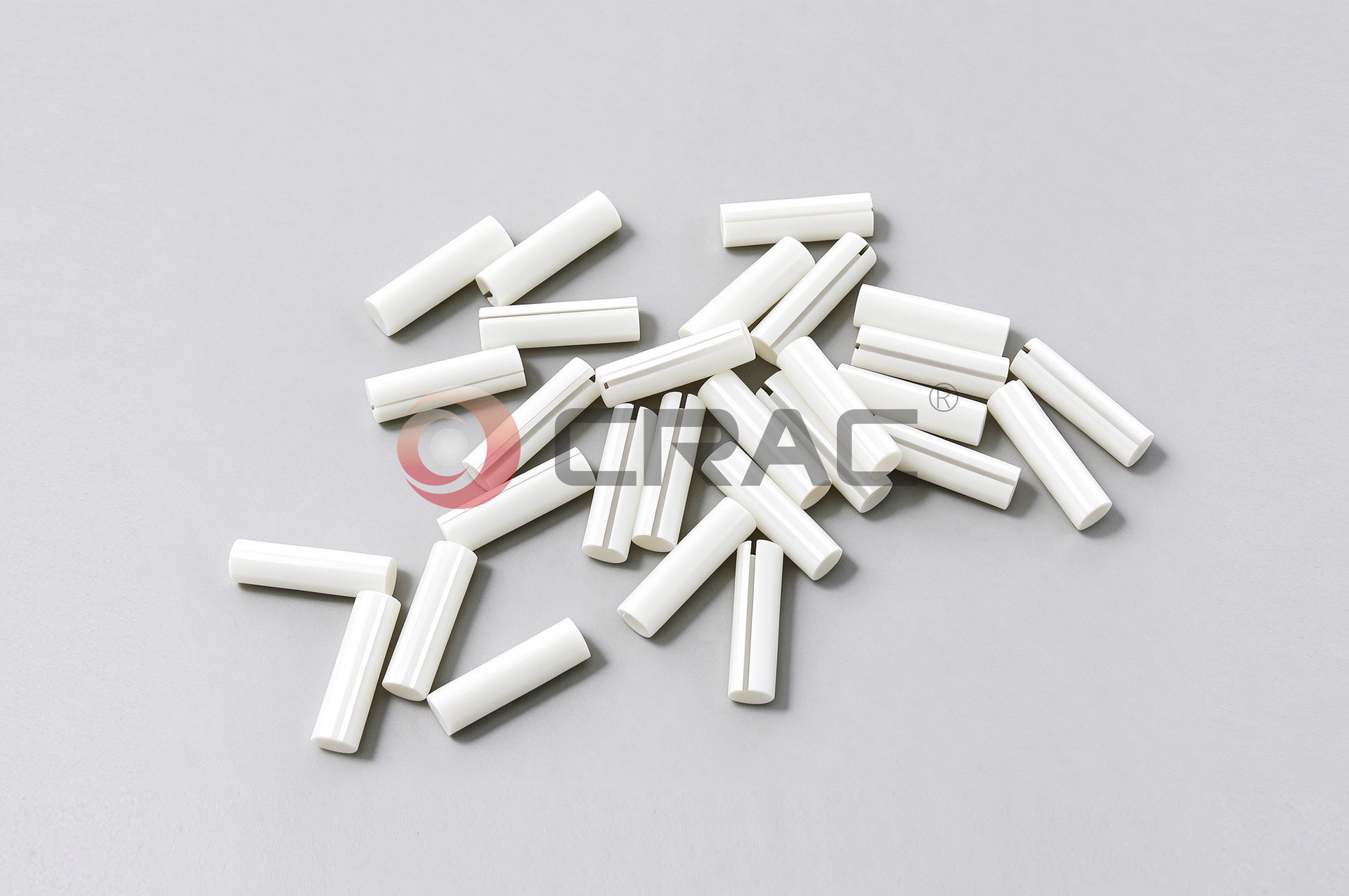
Four Numbers That Compete for One Budget
On a conventional single-mode ferrule the outer diameter sits at 2.499 mm with a half-micron band, the bore runs a few tenths of a micron over the 125 micron fibre it has to accept, concentricity between bore and OD is held near one micron, and the end face carries a radius, an apex offset and a fibre height. Each of these is measurable and each will be quoted. What is rarely quoted is which of them the molder is actually controlling, and where the rest of the error comes from.
The useful way to read the drawing is to ask, for each tolerance, which process creates it and which process can still correct it. Errors created late are cheap; errors created early and inherited are expensive.
Where Each Micron Goes
The chain from feedstock to finished ferrule has five stages that matter dimensionally. The table below is the budget in the order it is spent, and it explains why a plant that can hold one micron on a diameter may still be unable to hold it on a relationship.
| Stage |
What it fixes |
What it spends |
| Molding | Green-body shape, bore position | Tool wear drift over the mold's life; gate and weld-line asymmetry |
| Debinding and sintering | Density, strength, final hardness | 15 to 20 percent linear shrink, and the anisotropy between directions that becomes concentricity error |
| OD grinding | Outer diameter to the half-micron band | Locks in whatever bore-to-OD relationship the part arrived with, unless the bore is used as the datum |
| Bore honing | Bore size, roundness, bore finish | Wall section uniformity; a bore corrected after grinding can pull the axis |
| End-face lapping | Radius, apex offset, fibre height, surface finish | Nothing upstream, but fixture angle error lands directly on return loss |
Read down the third column and the pattern is obvious: the two early stages create relationship errors, and the two late stages cannot remove them. That is the whole difficulty of the part.
Concentricity Is the Link You Cannot Buy Back
A diameter can be corrected by taking another pass. Concentricity cannot, because it is a relationship between two features, and grinding one feature to fix its size does not know where the other one is. The only lever is datum choice: grinding the OD with the bore as the reference, or boring with the OD held, and the two routes give different results on the same blank.
This is where near-net shaping earns its place. When the molded and sintered blank arrives with a small, uniform grinding allowance, the material removed from the wall is thin and even on both sides, so the axis does not shift as the diameter comes down. A blank with an uneven allowance has to be cut asymmetrically, and the wall that ends up thinner is the one that will also be weakest in service.
For conventional connectors, concentricity near one micron is the working target on single-mode parts and a looser band is normal on multi-mode. The hardware family is catalogued on the optical fibre ferrule page, and the broader sleeve and ferrule range sits on the ceramic sleeves and ferrules page.
The Bore Fit Nobody Writes Down
The gap between the 125 micron fibre and the bore is usually specified as a bore size with a tolerance, and almost never as what it actually is: an alignment allowance. A bore too tight will not accept the fibre without force, and forcing it damages the end face before the connector is ever mated. A bore too loose lets the fibre sit off-axis inside the hole, and that off-axis position is added to concentricity as if the ferrule had been made worse.
Practically, the clearance is kept in the tenths of a micron, and the adhesive has to fill it without pushing the fibre off centre while curing. If your assembly process uses a particular adhesive viscosity or cure shrink, say so at enquiry — the bore size can be set around it rather than corrected afterwards by sorting.
End-Face Geometry: PC and APC Are Different Jobs
A physically contacting end face is a polished dome, typically in the 10 to 25 mm radius range, with the fibre height held within about a hundred nanometres of the surrounding ceramic and the apex offset inside roughly 50 microns. An angled physical contact face adds an 8 degree polish and a tighter radius band, and the angle is where the difficulty concentrates: the fixture that holds the ferrule during lapping contributes its own angular error, and that error goes straight into return loss.
Because the geometry is created at the last step, it is also the cheapest place to fix a problem — but only if the ceramic underneath is dense and uniform. A polished dome over a subsurface pore will not hold its figure through thermal cycling, and no amount of re-lapping recovers it.
Inspecting Incoming Ferrules: Five Checks That Actually Catch Problems
| Check |
Method |
What it reveals |
| Bore size and roundness | Air gauge, or pin gauge plus optical cross-section | Assembly force problems; ovality from sintering |
| Outer diameter | Micrometer with 0.1 micron resolution, or laser scan | Spring force in the adapter; gauge repeatability |
| Concentricity | Optical projector, or image measurement of bore versus OD | The alignment error that no polishing can remove |
| End-face geometry | Interferometer for radius, apex offset and fibre height | Insertion loss and return loss before you build the cable |
| Material and density | Density by immersion, colour and lot certificate | Sub-surface porosity that only shows up after polishing |
The fifth check is the one buyers skip and later regret. Two lots can pass every dimensional check and still differ in polishability, because one was sintered to a slightly lower density at the core. Immersion density on a sample per lot, tied to a certificate that names the grade, is inexpensive insurance.
Matching the Grade to the Chain, Not to the Hardness Table
The instinct is to pick the hardest material. On this part that instinct is wrong. Alumina reaches roughly 2000 HV at 99.7 percent purity and a density above 3.9 g/cm3, yet most ferrule production uses 3Y zirconia, which is softer at around 1200 HV but delivers bending strength above 1000 MPa and a density near 6.0 g/cm3. The reason is the wall: a ferrule is a thin tube with a 125 micron hole through it, and it has to survive honing, lapping, adhesive cure, crimping and years of spring load without chipping at the bore edge. Strength and toughness decide that, not hardness.
Around the two main grades sit the zirconia toughened aluminas at 10, 20 and 40 percent zirconia content, which trade some of the zirconia's toughness back for stiffness and cost, and zirconia toughened ruby where colour and wear resistance both matter. The comparison across families is set out in the zirconia parts material classification guide, and the same logic carries into micron-tolerance parts for medical devices and the wider ceramic medical parts range, where the wall thickness problem is identical.
When Molding Beats Pressing, and When It Does Not
Injection molding pays for itself when the part is small, has a bore that would otherwise need separate drilling, and runs in volume — because the tooling cost is spread over the batch and the near-net blank removes grinding stock from every piece. On a simple straight sleeve produced in thousands, dry pressing followed by grinding is often cheaper and just as good.
The decision line is grinding allowance multiplied by quantity. Ask what blank the supplier intends to start from: if the answer is a pressed cylinder with a drilled hole, the concentricity will be whatever the drilling and the OD grind happen to produce, and it will drift lot to lot. A molded bore holds its position relative to the outer form by construction, which is why the process detail matters more than the material data sheet. The molding route is described under precision ceramic injection molding.
What the Drawing Should Say
Six items turn a ferrule drawing into something that can be quoted and inspected without argument:
1. Datum. State whether concentricity is measured from the bore or the OD, and at what axial position.
2. Bore size with its assembly intent. Give the fibre diameter and the adhesive, not just a hole tolerance.
3. End-face callout. PC or APC, radius band, apex offset limit, fibre height window.
4. Grade and colour. Name the material family and the colour, since both are process outputs.
5. Surface finish at the bore and the face. A roughness limit is a separate requirement from a dimension.
6. Sampling and certificates. Which checks are 100 percent, which are sampled, and what document travels with the lot.
Non-standard diameters, sleeve forms and shaped bores can be molded to a drawing rather than selected from a range; that route runs through the OEM and ODM program and the custom zirconia structural parts capability. For parts that also see abrasive slurry or aggressive chemistry, the wear and corrosion case is covered separately under structural parts for extreme wear and corrosion, and the full sleeve and ferrule range is on the ceramic sleeves and ferrules index.
Send the drawing with the datum marked and we will confirm the achievable band.